Assembled ATtiny2313 serial terminal Design The ATmega8 terminal had two boards with a 14 conductor cable assembly between them. Breakaway Audio Enhancer Keygen Idm. The space occupied by the cable was greater than the space occupied by the two boards. On the ATtiny2313 version, the two boards mate directly, with no cable between. The display has two identical 18 position single row header pads, one on each long side of the PC board. Although only one is used to communicate with the LCD display, both have connectors in them for structural support. Additionally, spacers hold the boards at the correct distance for the connectors to mate reliably.

Easy ATTiny Serial Communication With Tiny AVR Programmer. Easy ATTiny Serial Communication With Tiny AVR. You could use the serial to discover the port. Can I use the AVR STK Serial Port Dongle Programmer (SKU#: PGM-00014) to program the ATtiny13 with WinAVR? It is not listed on the SparkFun site under supported devices: The currently supported devices by PonyProg software, which can be programmed by AVR-PG1B are: AT90S1200, AT90S2313, AT90S2323.
The connectors are the same type used on the Arduino, but are 18 position. Some of the alternatives require so much insertion force that I was afraid I might break the glass putting the boards together. An IRF7470 MOSFET is used to PWM the display backlight, which can be set from 1 to 15. The brightness of the display is set using the ALT-F3 and ALT-F4 keys. Timer0 in fast PWM mode supplies the 7.2kHz drive signal for the MOSFET. This MOSFET is a 'logic level' MOSFET, in that Vgs(th) is around 2 volts.
An emitter follower is used to set the contrast. I have found the spec for current at the Vo input for only one LCD display, and that was 0.8 mA. The range of the contrast control is extreme compared to the Vo voltage required. The real Vo voltage range is around VDD-4.0 to VDD-5.0 (+1V to 0V). If you're interested, there is an inverter in the display controller that turns that into a negative voltage for the LCD 'glass' bias, somewhere around (Vdd-7)V. I'm not sure how or why it is referenced to VDD.
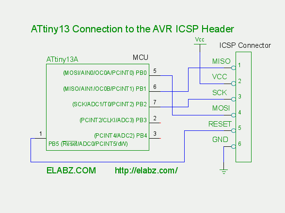
There are a few things I have started doing on all of my projects to make development easier: • A 12 VDC wall wart • A TO-220 package voltage regulator with a blocking diode • A 10-pin ISP connector • A 6-pin serial connector pinned out to accept the FTDI cable (or this terminal!) I switched to a 9VDC wall wart for this project. The voltage regulator must supply current to the ATtiny2313, the backlight, and the keyboard. Altogether it is around 500 mA. The dissipation in the regulator is (12-5)x0.5 = 3.5W, which makes it hot, even with a 9VDC wall wart it is (9-5)x0.5 = 2W, so a little copper strip on the PC board is used as a heatsink. Also, the 9VDC wart provides 1.5A, rather than the 500mA of the 12VDC model. Also, the 6-pin connector is not required on this project because this is the device on the other end of the 6-pin cable. A 4-pin mini-din connector is onboard for serial connection to the outside world.